Request A Quote
Application

⚡ RF Connector & Electrical Parts

Precision CNC machined coaxial connector bodies, contact pins, interconnect housings — machined from brass and copper alloys

⏱ 3-5 monthsBrass C360Copper C110Beryllium copperStainless 303

Typical Parts We Machine

  • RF coaxial connector bodies
  • Contact pins and sockets
  • Interconnect housings and shells
  • Insulator supports and spacers
  • Custom electrical contact assemblies
  • Precision threaded connector parts

Materials

Brass C360 · Copper C110 · Beryllium copper · Stainless 303. Full material certs available on request.

Quality

Every part is CMM-inspected with full report included. Cpk ≥ 1.33 on critical dimensions. Free FAI with every new part.

Related Parts
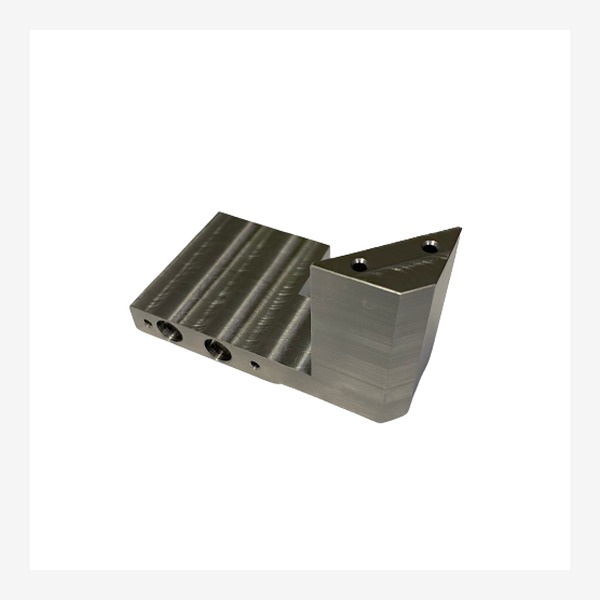
Part
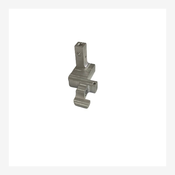
Part
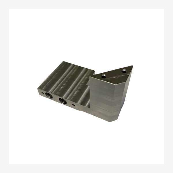
Part

Explore Related Industries

These precision machining tracks share similar processes, materials, and quality standards.

Frequently Asked Questions

What materials are best for RF connectors?

The standard materials for RF connectors are: brass (C36000) for bodies — excellent machinability and conductivity; beryllium copper (C17200) for center contacts — good spring properties; phosphor bronze for grounding springs; and PTFE/Teflon for dielectric insulators. We also machine aluminum and stainless steel for specialized RF housings.

What surface finishes do you apply to RF connector parts?

For RF performance, we offer: gold plating over nickel (per MIL-DTL-45204) for low contact resistance; silver plating (per ASTM B700) for high-frequency applications up to 18GHz; electroless nickel for corrosion resistance; and passivation for stainless steel parts. Plating thickness is verified with XRF measurement and documented.

What tolerances do you hold on RF center contacts?

We hold ±0.02mm on contact pin diameters and ±0.05mm on insulator pocket dimensions. For impedance-critical dimensions (50 ohm / 75 ohm), we maintain ±0.03mm on the center conductor-to-outer conductor gap. Dimensional consistency across production runs is verified with CMM and optical measurement.

Do you machine both male and female RF connector types?

Yes. We machine both pin (male) and socket (female) contacts for SMA, SMB, BNC, TNC, N-type, 7-16 DIN, MCX, MMCX, SMP, and 2.92mm/2.4mm/1.85mm connectors. We also machine custom and proprietary connector geometries for defense and telecom applications.

Can you machine the dielectric/insulator components too?

Absolutely. We machine PTFE (Teflon), PEEK, and PEI (Ultem) insulators with tolerances of ±0.03mm. PTFE machining requires specialized tooling and techniques to achieve smooth surfaces without tearing — our machinists have decades of experience with PTFE and other engineering plastics for RF applications.

What is your typical lead time for RF connector components?

Custom RF connector prototypes: 3-5 working days. Production quantities (500-10,000+): 2-4 weeks depending on complexity and plating requirements. For short-run production with standard materials and plating, we offer competitive lead times of 7-10 working days. Volume pricing is available for production orders.

Buying Guide

RF Connector CNC Machining — Plating, Impedance & Precision Threads

1. Thread Precision Affects Signal Integrity

RF connector threads (SMA, N-type, BNC, TNC) must meet MIL-STD-348 or IEC 60169 standards. TruPart machines threads to Class 2A/2B fit with CMM thread inspection.

2. Plating Selection Is Critical

Gold plating over nickel underplate remains the standard for RF connectors requiring corrosion resistance and low contact resistance. Silver plating offers lower insertion loss at higher frequencies.

3. Center Pin Concentricity

Signal reflection is minimized by tight concentricity between inner and outer conductors. TruPart holds concentricity within 0.025mm TIR on precision RF connector assemblies.

4. Dielectric Support Design

The dielectric support bead geometry directly affects impedance matching. PTFE and PEI are common dielectric materials that TruPart machines to precise dimensions for 50 ohm impedance matching.

5. Plating Thickness Uniformity

Non-uniform plating causes impedance discontinuities across the connector. Specify plating thickness tolerance and require cross-section measurement on first articles to verify uniformity.

×

Ready to Start Your Project?

Send us your drawing. We'll review, optimize, and quote within one business day.

Request A Quote

STEP · IGES · PDF · SolidWorks · DWG